Every networking professional has had to memorize the OSI model at some point. “Please Do Not Throw Sausage Pizza Away”: Physical, Data Link, Network, Transport, Session, Presentation, Application. It’s the first thing you learn in any networking course and the last thing people think about during actual troubleshooting.
Which is a shame, because the OSI model isn’t just an academic exercise. It’s a mental framework that, when properly internalized, makes you dramatically faster at diagnosing network problems. I’ve been troubleshooting networks for over 30 years, and I still think in OSI layers when something breaks. “Is this a Layer 2 problem or a Layer 3 problem?” is usually the first question I ask, and getting that right cuts your debugging time in half.
Let me walk through each layer with real-world examples, not just the textbook definitions, but how each layer actually manifests in the networks you work with every day.
The OSI Model at a Glance
| Layer | Name | What It Does | Example Protocols/Tech |
|---|---|---|---|
| 7 | Application | User-facing services | HTTP, SMTP, DNS, FTP, SSH |
| 6 | Presentation | Data format translation | TLS/SSL, JPEG, ASCII, compression |
| 5 | Session | Connection management | NetBIOS, RPC, SOCKS |
| 4 | Transport | End-to-end delivery | TCP, UDP, QUIC |
| 3 | Network | Logical addressing & routing | IP, ICMP, OSPF, BGP |
| 2 | Data Link | Physical addressing & framing | Ethernet, Wi-Fi (802.11), ARP |
| 1 | Physical | Bits on the wire | Cables, fiber, radio signals, hubs |
The model works bottom-up: each layer provides services to the layer above it and uses services from the layer below. When you send an HTTP request, it passes down through all seven layers on your machine, traverses the network, and passes back up through all seven layers on the server.
Layer 1: Physical (Bits, Wires, and Light)
The Physical layer is about getting raw bits from point A to point B. It defines:
- Physical medium: Copper (Cat5e/Cat6), fiber optic (single-mode/multi-mode), wireless (radio waves)
- Signaling: How 1s and 0s are represented (voltage levels, light pulses, radio modulation)
- Connectors and pinouts: RJ45, SC, LC, SFP+
- Data rates and distances: 1G over 100m of Cat6, 10G over 300m of OM3 multimode fiber
Real-World Layer 1 Problems
Layer 1 problems are the most frustrating because they’re intermittent and hard to diagnose with software. A crimped cable with a slightly damaged pair will work fine for small packets but start dropping large frames. A dirty fiber connector will show increasing bit errors under high load. A Wi-Fi access point placed too close to a microwave oven will have mysterious packet loss at lunchtime (I wish I were joking; this actually happened).
Pro tip: When debugging network issues, always start at Layer 1. Check the physical link. Look for amber/red lights on switch ports. Run cable diagnostics. Check SFP module compatibility. I’ve seen engineers spend hours debugging a “routing problem” that turned out to be a bad patch cable.
Layer 1 Devices
- Hubs: Repeat electrical signals to all ports (essentially dead technology)
- Media converters: Convert between copper and fiber
- Repeaters/amplifiers: Boost signal strength over long distances
Layer 2: Data Link (Frames and MAC Addresses)
The Data Link layer is responsible for reliable node-to-node data transfer across a single physical link. It handles framing, physical addressing (MAC addresses), error detection, and access control.
Sublayers
IEEE 802 divides Layer 2 into two sublayers:
- LLC (Logical Link Control): Multiplexing protocols transmitted over the MAC layer, flow control, error notification
- MAC (Media Access Control): Physical addressing, frame delimiting, channel access (CSMA/CD for Ethernet, CSMA/CA for Wi-Fi)
Ethernet Frames
The dominant Layer 2 protocol is Ethernet (IEEE 802.3). An Ethernet frame looks like:
| Preamble | Dest MAC | Src MAC | 802.1Q Tag | EtherType | Payload | FCS |
| 8 bytes  | 6 bytes  | 6 bytes | 4 bytes    | 2 bytes   | 46-1500 | 4 bytes |
MAC addresses are 48-bit (6-byte) addresses, usually written as 00:1A:2B:3C:4D:5E. The first 3 bytes identify the manufacturer (OUI, or Organizationally Unique Identifier), and the last 3 are assigned by the manufacturer. This is why you can often identify device types by their MAC address prefix.
VLANs: Virtual Segmentation at Layer 2
VLANs (Virtual LANs) are Layer 2’s most important feature for network design. A VLAN lets you logically segment a physical network into separate broadcast domains. The 802.1Q standard adds a 4-byte tag to the Ethernet frame that identifies which VLAN it belongs to.
# Cisco switch VLAN configuration
interface GigabitEthernet0/1
 switchport mode access
 switchport access vlan 10
!
interface GigabitEthernet0/24
 switchport mode trunk
 switchport trunk allowed vlan 10,20,30
Layer 2 Gotcha: Broadcast Storms
Layer 2 loops are catastrophic. Unlike Layer 3 (where TTL prevents infinite loops), Layer 2 has no built-in loop prevention in the frame header. A single miscabled connection that creates a loop will generate a broadcast storm that can take down an entire VLAN in seconds. I’ve seen this happen in production. One redundant uplink without STP (Spanning Tree Protocol) brought an entire campus network to its knees.
Spanning Tree Protocol (STP) and its modern variants (RSTP, MSTP) exist to prevent loops, but they’re complex and have their own failure modes. Modern data center fabrics use Layer 3 routing all the way to the access layer (L3 leaf-spine) specifically to avoid Layer 2 loop problems.
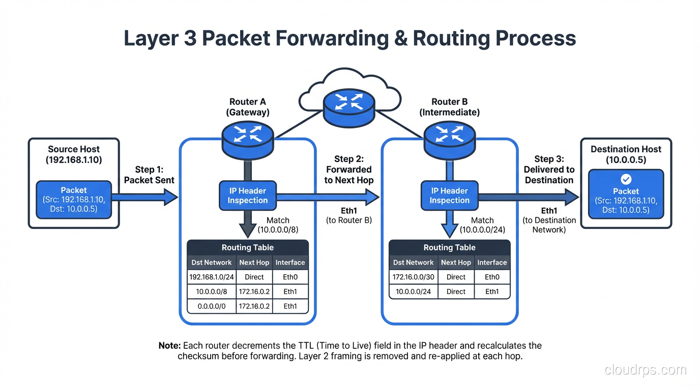
Layer 3: Network (IP Addresses and Routing)
Layer 3 is where the internet happens. It’s responsible for logical addressing (IP addresses) and routing, getting packets from source to destination across multiple networks.
IP Addressing
IPv4 uses 32-bit addresses (4.3 billion possible), while IPv6 uses 128-bit addresses (3.4 x 10^38, enough for every grain of sand on Earth). We’ve been “running out” of IPv4 since 2011, kept alive by NAT and the market for used IPv4 blocks.
Routing
Routers operate at Layer 3. They examine the destination IP address, consult their routing table, and forward the packet toward its destination. This is where routing protocols like OSPF and BGP come in. They’re the mechanisms by which routers share information about which networks they can reach.
ICMP: The Diagnostic Protocol
ICMP (Internet Control Message Protocol) lives at Layer 3 and provides error reporting and diagnostic capabilities. ping uses ICMP Echo Request/Reply. traceroute uses ICMP Time Exceeded messages (or UDP probes on Unix).
Layer 3 Devices
- Routers: Forward packets between networks based on IP addresses
- Layer 3 switches: Switches that can also route, common in campus networks
- Firewalls (basic): Packet-filtering firewalls operate at Layer 3/4
Real-World Layer 3 Debugging
# Check if you can reach a host (Layer 3 connectivity)
ping -c 4 10.0.1.1

# Trace the path packets take
traceroute 10.0.1.1

# Check your routing table
ip route show          # Linux
netstat -rn            # macOS/BSD
show ip route          # Cisco
If ping works but your application doesn’t, you know Layer 3 is fine and the problem is higher up the stack (probably Layer 4 or Layer 7).

Layer 4: Transport (TCP, UDP, and Ports)
Layer 4 is where things get interesting from an application perspective. The Transport layer provides end-to-end communication between processes, not just between hosts. This is achieved through port numbers, a 16-bit value (0-65535) that identifies a specific application or service on a host.
For a deep dive into TCP and UDP, see our complete guide to transport layer protocols.
TCP vs UDP Quick Comparison
| Feature | TCP | UDP |
|---|---|---|
| Connection | Connection-oriented (3-way handshake) | Connectionless |
| Reliability | Guaranteed delivery, ordering, retransmission | Best-effort, no guarantees |
| Flow control | Yes (sliding window) | No |
| Overhead | Higher (20+ byte header) | Lower (8-byte header) |
| Use cases | Web, email, file transfer, SSH | DNS, video streaming, gaming, VoIP |
The Importance of Layer 4 in Modern Infrastructure
Layer 4 vs Layer 7 is one of the most important distinctions in modern infrastructure. Layer 4 load balancers route based on IP and port, while Layer 7 load balancers can inspect application-layer data. Understanding which layer you’re operating at determines your capabilities, performance, and failure modes.
Layer 4 Debugging
# Check what's listening on which ports
ss -tlnp                          # Linux
netstat -an | grep LISTEN          # macOS

# Test TCP connectivity to a specific port
nc -zv 10.0.1.1 443               # netcat
telnet 10.0.1.1 443               # old school

# Capture packets at Layer 4
tcpdump -i eth0 'tcp port 443'    # filter TCP on port 443
Layer 5: Session (The Controversial Layer)
Here’s where the OSI model gets a bit… academic. The Session layer manages sessions, which are ongoing stateful interactions between applications. It’s responsible for establishing, maintaining, and terminating sessions, as well as synchronization (checkpointing so a large transfer can resume from where it left off).
Does Layer 5 Really Exist?
In the TCP/IP model (which is what the actual internet uses), there is no separate Session layer. TCP handles session management through its connection lifecycle (SYN, established, FIN). Most protocols we use daily don’t have a cleanly separable session layer.
That said, some protocols do have distinct session management:
- RPC (Remote Procedure Call): Manages request-response sessions
- SMB/CIFS: File sharing sessions with authentication state
- SIP (Session Initiation Protocol): For establishing VoIP sessions
- TLS session resumption: Allows reuse of previously negotiated security parameters
I’ll be honest: in 30+ years, I’ve never debugged a problem and said “ah, this is a Layer 5 issue.” It’s either a Layer 4 problem (TCP connection management) or a Layer 7 problem (application logic). The Session layer is the most theoretical of all seven layers.
Layer 6: Presentation (Data Translation and Encryption)
The Presentation layer handles data format translation, encryption/decryption, and compression. It ensures that data from the application layer of one system can be read by the application layer of another.
Real-World Layer 6 Functions
- TLS/SSL encryption: The encryption that protects your HTTPS connections happens at Layer 6 (though it’s tightly integrated with Layer 5 session management and Layer 7 application protocol)
- Character encoding: ASCII to EBCDIC conversion (mostly historical), UTF-8 handling
- Data serialization: Converting between formats like JSON, XML, Protocol Buffers
- Compression: gzip, Brotli content encoding in HTTP
- Image/media encoding: JPEG, PNG, H.264, including format negotiation and transcoding
The TLS/SSL Example
TLS is the clearest real-world example of Layer 6 in action. When your browser connects to a website over HTTPS:
- Layer 7 (HTTP) generates the request
- Layer 6 (TLS) encrypts the request
- Layer 5 (Session) manages the TLS session
- Layer 4 (TCP) segments and delivers the encrypted data
In practice, TLS spans Layers 5-6 and is negotiated at the start of the TCP connection (or during, with STARTTLS). This blurriness is why the TCP/IP model doesn’t bother separating these layers.
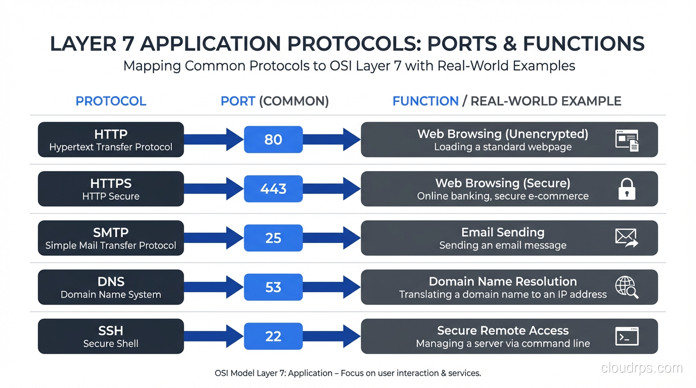
Layer 7: Application (Where Users Live)
The Application layer is where the protocols you interact with daily operate. This is the layer that provides services directly to the end user or application.
Common Layer 7 Protocols
| Protocol | Port | Purpose |
|---|---|---|
| HTTP/HTTPS | 80/443 | Web traffic |
| DNS | 53 | Name resolution |
| SMTP | 25/587 | Email sending |
| IMAP | 143/993 | Email retrieval |
| SSH | 22 | Secure remote access |
| FTP | 20-21 | File transfer (please don’t) |
| DHCP | 67-68 | IP address assignment |
| SNMP | 161-162 | Network management |
| NTP | 123 | Time synchronization |
Layer 7 in Modern Infrastructure
Layer 7 is where most of the interesting work happens in modern cloud architectures:
- API gateways operate at Layer 7, routing requests based on URL paths, headers, and methods
- WAFs (Web Application Firewalls) inspect Layer 7 content for SQL injection, XSS, and other attacks
- Content delivery networks cache and serve content based on Layer 7 information (URL, cookies, headers)
- Service meshes (Istio, Linkerd) provide Layer 7 observability and routing between microservices
Layer 7 Debugging
# HTTP debugging
curl -v https://example.com        # verbose HTTP output
curl -I https://example.com        # headers only

# DNS debugging
dig example.com A                  # query A record
nslookup example.com               # simpler alternative

# HTTP/2 specific
curl --http2 -v https://example.com

# TLS debugging (Layer 6/7)
openssl s_client -connect example.com:443
OSI Model vs TCP/IP Model: What’s Actually Used
The dirty secret of networking education is that the internet doesn’t actually use the OSI model. It uses the TCP/IP model (also called the Internet Protocol Suite), which has only four layers:
| TCP/IP Layer | OSI Layers | Protocols |
|---|---|---|
| Application | 5, 6, 7 | HTTP, DNS, SMTP, SSH, TLS |
| Transport | 4 | TCP, UDP, QUIC |
| Internet | 3 | IP, ICMP, ARP* |
| Network Access | 1, 2 | Ethernet, Wi-Fi |
*ARP is debatable; it bridges Layers 2 and 3.
The TCP/IP model is what’s implemented in every operating system’s networking stack. The OSI model is a reference framework, useful for thinking about problems, but not a strict implementation guide.
Why the OSI Model Still Matters
Despite not being the actual implementation model, the OSI model persists because:
- It’s a shared vocabulary. When someone says “Layer 3 switch,” everyone knows what they mean.
- It’s a troubleshooting framework. Starting at Layer 1 and working up is a proven methodology.
- It separates concerns clearly. The seven-layer model does a better job of isolating responsibilities than the four-layer TCP/IP model.
- It appears on every certification exam. CCNA, CompTIA Network+, AWS Solutions Architect. They all test it.
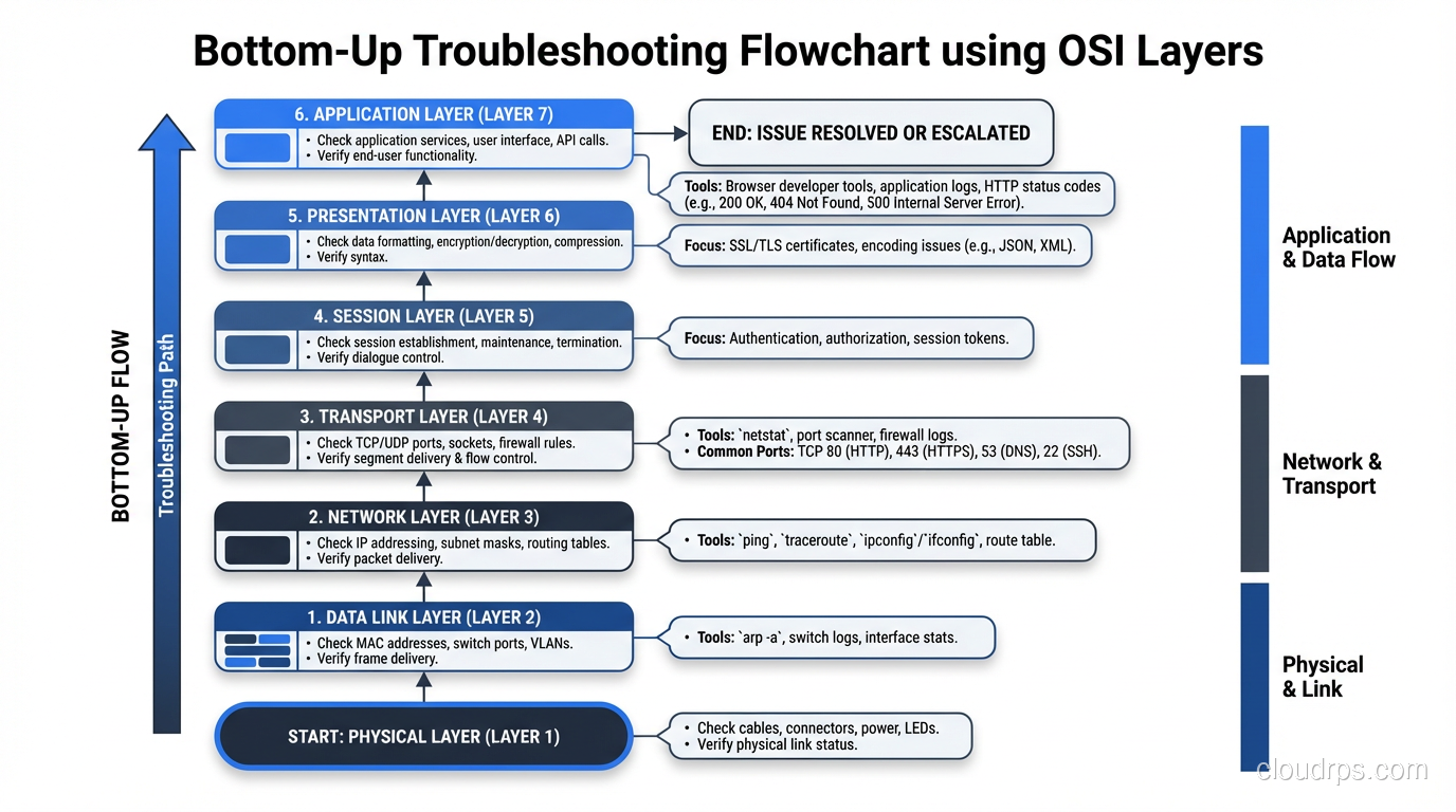
Troubleshooting with the OSI Model: A Practical Approach
Here’s my actual troubleshooting workflow when a “network issue” is reported:
Bottom-Up Approach
- Layer 1: Is the cable plugged in? Is the link light on? Any media errors on the interface?
- Layer 2: Is the MAC address in the switch’s CAM table? Are there VLAN mismatches? STP blocking?
- Layer 3: Can you ping the gateway? Is the route in the routing table? ARP resolving?
- Layer 4: Can you telnet/nc to the port? Are there firewall rules blocking? TCP resets?
- Layer 7: Is the service running? Is it returning errors? Check application logs.
I skip Layers 5 and 6 in practice. Their concerns are folded into Layer 4 (session) and Layer 7 (presentation/application).
Example: “The Website Is Down”
Step 1 (L1): Link lights? ✓ Green
Step 2 (L2): VLAN correct? ✓ Same VLAN as before
Step 3 (L3): Ping server IP? ✓ Ping works, 1ms
Step 4 (L4): TCP to port 443? ✗ Connection refused!
→ The web server process is down. Restart Nginx. Problem solved.
Without the OSI mental model, you might waste 30 minutes looking at DNS, checking routing tables, or blaming the CDN. The layered approach gets you to the answer faster.
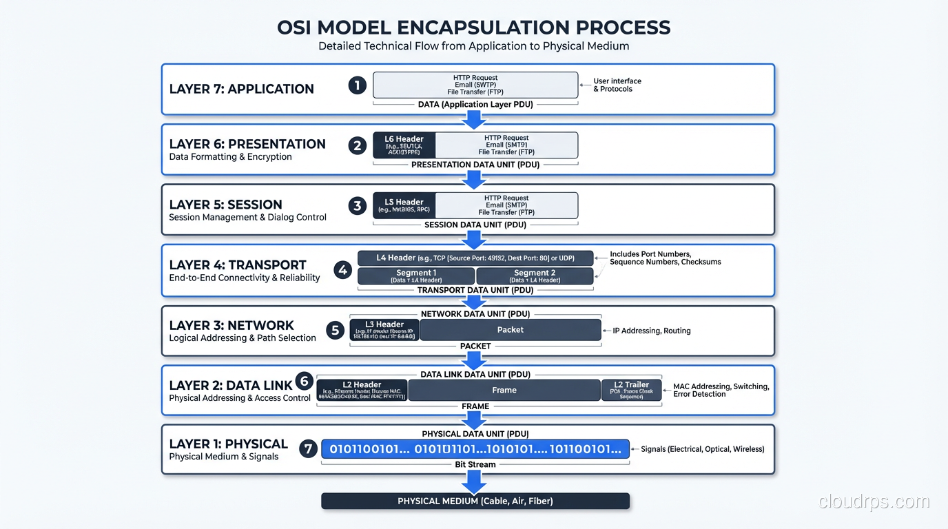
Encapsulation: How Data Moves Through the Layers
As data moves down the OSI stack, each layer adds its own header (and sometimes trailer). This process is called encapsulation:
Layer 7: [Data]
Layer 4: [TCP Header | Data] → "Segment"
Layer 3: [IP Header | TCP Header | Data] → "Packet"
Layer 2: [Ethernet Header | IP Header | TCP Header | Data | FCS] → "Frame"
Layer 1: 01001010110100... → "Bits"
On the receiving end, each layer strips its header and passes the remaining data up. This is de-encapsulation.
Understanding encapsulation explains why MTU (Maximum Transmission Unit) matters. Ethernet’s standard MTU is 1500 bytes, which is the maximum payload at Layer 2. But your IP packet has a 20-byte header, and TCP has another 20 bytes, leaving only 1460 bytes for application data (MSS, or Maximum Segment Size). Add TLS overhead and you’re down further. This is why Path MTU Discovery exists, and why misconfigured MTU causes the infuriating “large packets fail, small packets work fine” problem.
Wrapping Up
The OSI model is one of networking’s most enduring teaching tools, not because it perfectly maps to reality, but because it provides a clean mental framework for understanding how networks work and, more importantly, how to fix them when they don’t.
Key takeaways:
- Layers 1-4 are where 95% of troubleshooting happens. Know them cold.
- Layers 5-6 are mostly theoretical in the TCP/IP world. TLS spans both.
- Layer 7 is where modern application-layer infrastructure (API gateways, WAFs, CDNs) does its work.
- Always troubleshoot bottom-up. Don’t blame DNS until you’ve verified Layers 1-4.
- The TCP/IP model is what’s actually implemented; the OSI model is the reference framework.
Whether you’re debugging a connectivity issue, designing a new network, or sitting for a certification exam, thinking in layers will make you a better engineer. It’s been 40+ years since the OSI model was standardized, and it’s still the best tool we have for making complex networks comprehensible.
Get Cloud Architecture Insights
Practical deep dives on infrastructure, security, and scaling. No spam, no fluff.
By subscribing, you agree to receive emails. Unsubscribe anytime.