
“What’s the difference between a router and a switch?” It’s a question I’ve been asked in probably a hundred interviews over the years, and the answers I get reveal a lot about someone’s depth of understanding. The surface answer is easy: switches connect devices on the same network, routers connect different networks. But the real answer goes much deeper, and the line between the two has blurred significantly with modern hardware.
I’ve racked and stacked both, from early Catalyst 5000 switches that weighed as much as a small car to the latest Arista 7800R series that can push terabits per second. I’ve configured BGP on routers that held the full internet routing table and managed switch fabrics in data centers serving millions of users. The fundamentals matter, even in a world that’s increasingly software-defined.
Switches: The Local Connectors
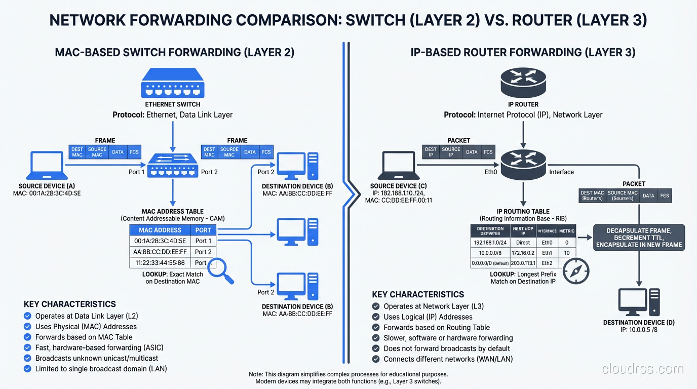
A network switch operates primarily at Layer 2 of the OSI model, the Data Link layer. Its job is to forward Ethernet frames between devices on the same local network (LAN) based on MAC addresses.
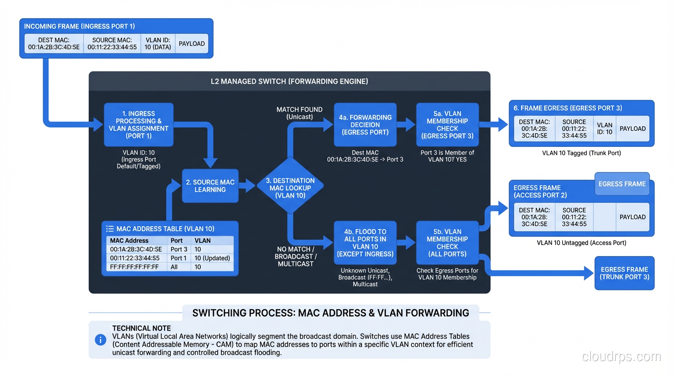
When a device sends a frame, the switch examines the destination MAC address and looks it up in its MAC address table (also called a CAM table, or Content Addressable Memory). If the MAC address is in the table, the switch forwards the frame only out the port where that device is connected. If the MAC address isn’t in the table, the switch floods the frame out all ports (except the one it came in on), and when the destination device responds, the switch learns which port it’s on.
This is fundamentally different from what a hub did (yes, hubs existed, and they were terrible). A hub sent every frame out every port, all the time. Switches are intelligent. They learn where devices are and send traffic only where it needs to go. This is why switches replaced hubs completely by the early 2000s.
How MAC Learning Works
The learning process is elegant in its simplicity:
- A frame arrives on port 1 from MAC address AA:BB:CC:DD:EE:01.
- The switch records: “MAC AA:BB:CC:DD:EE:01 is on port 1” in its MAC address table.
- The frame’s destination is MAC AA:BB:CC:DD:EE:02. The switch checks its table.
- If it finds an entry for AA:BB:CC:DD:EE:02 on port 5, it forwards the frame only to port 5.
- If there’s no entry, it floods the frame to all ports (except port 1). When the destination device responds, the switch learns its port.
MAC address table entries age out after a configurable timeout (typically 300 seconds). This handles devices being moved or disconnected without requiring manual intervention.
VLANs: Virtual Segmentation
One of the most important switch features is VLAN (Virtual LAN) support. VLANs let you create separate broadcast domains on the same physical switch. Devices in VLAN 10 can communicate with each other but can’t directly reach devices in VLAN 20, even if they’re plugged into the same switch.
VLANs are tagged using IEEE 802.1Q, which adds a 4-byte tag to the Ethernet frame header. Trunk ports carry traffic for multiple VLANs (with tags), while access ports are assigned to a single VLAN (tags are stripped). This is fundamental to modern network design. Without VLANs, you’d need a separate physical switch for every isolated network segment.
I can’t count how many network security incidents I’ve seen that trace back to misconfigured VLANs. A database server accidentally on the same VLAN as the guest WiFi network. A management VLAN that wasn’t properly isolated. VLANs are powerful, but they’re only as good as your configuration management.
Routers: The Network Connectors
A router operates at Layer 3, the Network layer. Its job is to forward IP packets between different networks based on IP addresses and routing tables.
While a switch asks “Which port has this MAC address?”, a router asks “Which network is this IP address on, and what’s the best path to get there?” These are fundamentally different questions, and they operate at different levels of the protocol stack.
When a packet arrives at a router:
- The router examines the destination IP address.
- It looks up the destination in its routing table, a collection of entries mapping network prefixes (CIDR blocks) to next-hop addresses or outgoing interfaces.
- It determines the best path based on the routing table (which was built through static configuration or dynamic routing protocols like OSPF, BGP, or EIGRP).
- It decrements the TTL (Time to Live) in the IP header. If the TTL reaches zero, the packet is dropped and an ICMP “Time Exceeded” message is sent back. This prevents routing loops.
- It rewrites the Layer 2 header. The source MAC becomes the router’s outgoing interface MAC, and the destination MAC becomes the next hop’s MAC.
- The packet is forwarded out the appropriate interface.
Step 5 is crucial and often overlooked. When a packet crosses a router, the MAC addresses change but the IP addresses stay the same (unless NAT is involved). This is the fundamental difference between Layer 2 forwarding (switches) and Layer 3 forwarding (routers). For more on how routing protocols build these routing tables, we’ve covered that topic in detail.
The Routing Table
The routing table is the brain of the router. It contains entries like:
Destination        Next Hop         Interface    Metric
10.1.0.0/16       10.0.0.1        eth0         10
10.2.0.0/16       10.0.0.2        eth1         20
192.168.0.0/24    directly connected  eth2     0
0.0.0.0/0         10.0.0.254      eth0         100
The last entry, 0.0.0.0/0, is the default route. If no more specific route matches, the packet goes there. This is typically the path to the internet or to the upstream network.
Routes come from three sources:
- Directly connected networks (automatically added for each interface)
- Static routes (manually configured by an administrator)
- Dynamic routing protocols (learned automatically from neighboring routers)
In enterprise and data center environments, dynamic routing protocols are essential. OSPF within a site, BGP between sites and with internet peers. The routing protocol continuously updates the routing table as network topology changes: links go up or down, paths become congested, new routes are advertised.
The Blurry Line: Layer 3 Switches
Here’s where things get interesting. Modern enterprise switches almost universally support Layer 3 routing in addition to Layer 2 switching. These are called Layer 3 switches or multilayer switches.
A Layer 3 switch can do everything a Layer 2 switch does (MAC-based forwarding, VLANs, STP) AND everything a router does (IP-based forwarding, routing protocols, ACLs). In hardware. At wire speed. This blurred the line between switches and routers starting in the late 1990s, and today, the distinction is largely about form factor and deployment context rather than capability.
In a modern data center, the “switches” in the leaf-spine fabric are all Layer 3 devices running BGP. In a campus network, the “core switches” are routing between VLANs at 10/40/100 Gbps. They’re switches that route and routers that switch.
So when does the distinction still matter?
When You Need a “Router”
- WAN connectivity: Connecting to the internet, MPLS circuits, or remote sites. WAN routers handle diverse interface types (Ethernet, serial, cellular), VPN termination, NAT, and traffic shaping.
- Edge security: Edge routers integrate with firewalls, IPS, and DDoS mitigation. They’re the first line of defense.
- BGP peering: Internet-facing routers that peer with ISPs and IXPs need full BGP table support (1M+ routes) and the memory and CPU to handle it.
- Complex routing policy: When you need granular route filtering, redistribution between protocols, traffic engineering, or policy-based routing.
When You Need a “Switch”
- High-density LAN connectivity: Connecting dozens or hundreds of end devices (servers, workstations, access points) at high speed.
- Data center fabric: Leaf-spine architectures use high-port-count switches optimized for east-west traffic.
- Low-latency forwarding: Purpose-built switches use custom ASICs that forward packets in microseconds. General-purpose routers typically have higher per-packet latency.
- PoE (Power over Ethernet): Switches that power IP phones, cameras, and access points.
Spanning Tree: The Switch’s Nemesis
Switches have a challenge that routers don’t: broadcast loops. In a Layer 2 network, if there’s more than one path between two switches and no loop prevention, broadcast frames will circulate endlessly, consuming all bandwidth and crashing the network. I’ve seen this happen in production. It’s spectacular and terrifying. The network goes from working to completely dead in about two seconds.
Spanning Tree Protocol (STP) prevents loops by logically disabling redundant paths. It builds a tree topology where there’s exactly one active path between any two switches. If a link fails, STP recalculates and activates a previously disabled path.
The problem is that STP is slow. Classic STP (802.1D) takes 30-50 seconds to converge after a topology change. That’s 30-50 seconds of potential outage while the network recalculates. Rapid STP (802.1w) improved convergence to seconds, and MSTP (802.1s) added per-VLAN spanning tree instances. But STP remains one of the most common causes of network instability in Layer 2 environments.
This is one reason modern data center designs minimize Layer 2 domains. A leaf-spine architecture with Layer 3 routing at every switch eliminates STP entirely. Each switch is a router, and IP routing handles path selection and redundancy far more gracefully than STP ever could.
The OSI Model Connection
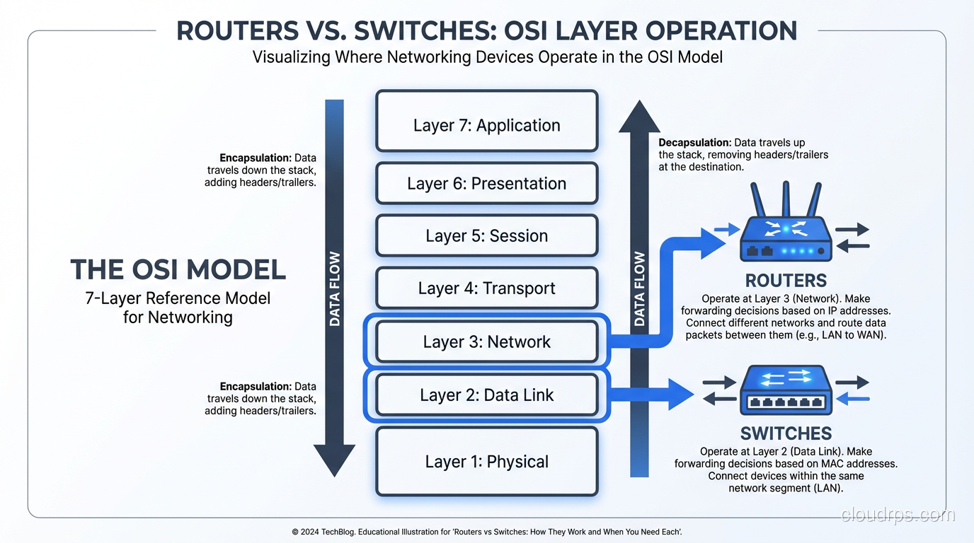
Understanding where routers and switches fit in the OSI model’s seven layers is essential for grasping why they behave differently.
Layer 1 (Physical): Cables, optics, electrical signals. Both switches and routers have physical interfaces, but they don’t operate at this layer; they consume it.
Layer 2 (Data Link): Ethernet frames, MAC addresses, VLANs. This is the switch’s primary domain. Switches make forwarding decisions based on Layer 2 information.
Layer 3 (Network): IP packets, IP addresses, routing. This is the router’s primary domain. Routers make forwarding decisions based on Layer 3 information.
Layer 4+ (Transport and above): TCP/UDP ports, application data. Traditional switches and routers don’t look this deep. But modern Layer 4 and Layer 7 load balancers do, and they blur the lines even further.
Real-World Architecture: How They Work Together
Let me walk through a typical enterprise network to show how switches and routers work together.
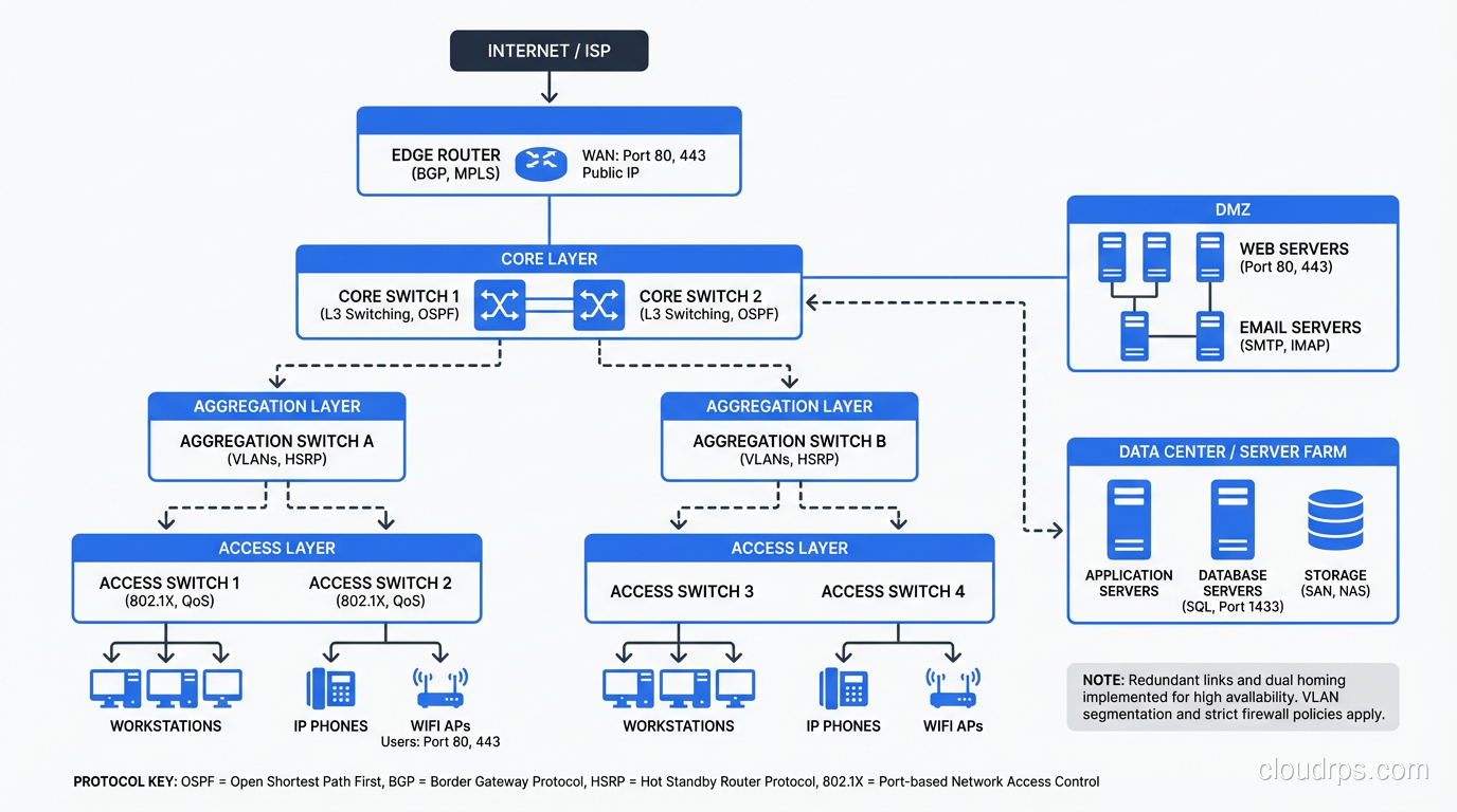
Access Layer
Users and devices connect to access switches. These are Layer 2/3 switches with 24 or 48 ports, usually supporting PoE for phones and access points. Each access switch has one or two uplinks to the distribution/aggregation layer. Ports are assigned to VLANs: one for user workstations, one for VoIP, one for printers, one for IoT devices.
Distribution/Aggregation Layer
Distribution switches aggregate traffic from multiple access switches. These are high-performance Layer 3 switches that route between VLANs and apply policy (QoS, ACLs). In modern designs, this layer is sometimes collapsed into the access layer (each access switch routes directly to the core).
Core Layer
Core switches provide high-speed backbone connectivity. In a campus, these might be a pair of redundant modular switches providing 100 Gbps+ throughput. In a data center, this is the spine layer of the leaf-spine fabric. Core switches route, they don’t typically do much policy enforcement. They just forward as fast as possible.
WAN Edge
WAN routers connect the campus or data center to the outside world. They terminate VPN tunnels, perform NAT, connect to ISPs, and enforce WAN-specific policy. This is where you typically still see dedicated router hardware rather than switches.
Firewall
Between the core and the WAN edge (and sometimes between internal segments), firewalls provide stateful packet inspection, intrusion prevention, and application-layer filtering. Firewalls are neither switches nor routers, though they do both switching and routing as part of their function.
Software-Defined Networking and the Future
The physical distinction between switches and routers is becoming less relevant as networking moves toward software-defined models.
In the cloud, there are no physical switches or routers that you manage. AWS VPCs, Azure VNets, and GCP VPCs provide both switching (devices in the same subnet communicate at Layer 2) and routing (traffic between subnets is routed) as software abstractions. The underlying physical network is managed by the cloud provider.
With SD-WAN, the WAN router’s intelligence moves to software controllers. The hardware becomes a commodity platform running software that makes routing decisions based on application policy, not just IP prefixes.
With network virtualization (VMware NSX, Cisco ACI), switching and routing happen in software overlays on top of the physical network. The physical network provides IP connectivity, and the virtual network handles segmentation, policy, and multi-tenancy.
But here’s the thing: the principles don’t change. Whether the switch is a physical Arista box or a virtual switch in a hypervisor, it’s still doing MAC-based forwarding. Whether the router is a dedicated Juniper platform or a software function in a cloud VPC, it’s still doing longest-prefix-match IP forwarding. Understanding the fundamentals of switching and routing is essential regardless of whether the implementation is hardware or software.
Common Misconceptions
“Switches are faster than routers.” This was true in the 1990s when routing was done in software on the CPU. Modern routers use ASICs for forwarding and can match switch speeds. In a leaf-spine data center fabric, the “switches” are routing at line rate.
“Routers are more secure than switches.” Neither is inherently more secure. Security comes from proper configuration: ACLs, firewall rules, segmentation. A misconfigured router is just as dangerous as a misconfigured switch.
“I only need switches for a small network.” You always need routing, even on a small network. The question is whether the routing is done by a dedicated router, a Layer 3 switch, or your firewall. Something has to be the default gateway.
“WiFi access points are switches.” Access points bridge wireless clients to the wired network, which is conceptually similar to switching, but modern APs are much more complex. They handle authentication, encryption, roaming, band steering, and often tunneling back to a wireless controller.
Choosing the Right Hardware
When specifying network equipment:
Port density and speed: How many devices need to connect, and at what speed? Access switches: 1G to users, 10/25G uplinks. Distribution/core: 25/40/100G. Data center leaf: 25/100G server-facing, 100/400G spine-facing.
Feature requirements: Do you need advanced routing protocols (BGP, OSPF)? Layer 3 multicast? MACsec encryption? sFlow/NetFlow? Not all switches support all features.
Power budget: If you’re powering phones and APs via PoE, calculate the total power budget carefully. A 48-port PoE+ switch at full load draws 740W. That adds up across a building.
Management and automation: Can you manage it through your existing NMS? Does it support NETCONF/YANG, REST APIs, gNMI? In 2024, if a switch doesn’t have an API, it doesn’t belong in your network.
Vendor ecosystem: Mixing Cisco switches with Arista routers with Juniper firewalls is possible but increases operational complexity. Consider the value of a unified management plane.
Wrapping Up
Routers and switches are the fundamental building blocks of every network, from a home office to a hyperscale data center. Switches forward frames based on MAC addresses within a network. Routers forward packets based on IP addresses between networks. In practice, modern hardware blurs this distinction (Layer 3 switches route, and routers switch), but the underlying principles remain distinct and important.
Understanding when and why to use each, how they interact, and how they fit into a larger architecture is foundational knowledge for any infrastructure engineer. The hardware is becoming more capable and the line between devices is blurring, but the questions remain the same: How does traffic get from A to B? Which layer makes the forwarding decision? Where do broadcast domains begin and end?
Master those questions, and the choice between a router and a switch (or increasingly, a device that does both) becomes straightforward.
Get Cloud Architecture Insights
Practical deep dives on infrastructure, security, and scaling. No spam, no fluff.
By subscribing, you agree to receive emails. Unsubscribe anytime.